|
| |
Motorized Goniometer Stage
|
|
Home
>
Motorized Goniometer Stages
|
|
This motorized goniometer is made of aluminum alloy with an
black anodized surface.
The bench size is 120 mm X 130 mm and has a body weight of 9 kg.
The drive mechanism is worm and worm gear. The worm gear ratio is
1 Deg (stage) : 304 Deg (motor)
.
It provides +/-15 Deg of rotation at a maximum speed of 5 degrees per second.
The maximum load of this goniometer table is 15 kg.
The calibrated indicator shows the angle of rotation.
The knob mounted on the motor allows for manual adjustment. This knob may be replaced with an optical encoder for precision position verification.
T
his stage requires a
Motion Controller
that can be ordered as a complete plug-and-play system with RS-232, USB, joystick and keypad control.
.
Specifications
|
Type
|
AK140-15
|
|
Range of Travel |
+/-15 Deg. |
|
Table Size |
120 mm x130 mm
|
|
Gear Ratio |
1 Deg (stage) : 304 Deg (motor)
|
|
Height of Rotation from the Top Surface |
118.3 mm +/-0.2 mm |
|
Drive Mechanism |
Worm Gear |
|
Travel Guide
|
Crossed-roller Guide |
|
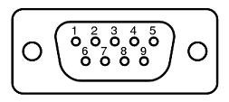
DB-9 Male Connector

|
|
Two-Phase Stepper Motor
|
|
Typical Phase Resistance
|
2.5 Ohms, Bi-directional
|
| Typical Phase Current |
2 Amp |
| |
|
Pin Assignment and Description
|
| 1 |
+5 VDC for the Limit Sensors |
| 2 |
CCW Limit Switch
The knob turns counter clockwise
Open Collector
Normally Open
Needs Pull up Resistor (typically 1000 Ohms)
|
| 3 |
CW Limit Switch
The knob turns clockwise
Open Collector
Normally Open
Needs Pull up Resistor (typically 1000 Ohms)
|
| 4 |
Return for+5 VDC
|
|
5
|
Not Connected
|
|
6
|
Stepper Motor Phase A+ |
| 7 |
Stepper Motor Phase A- |
| 8 |
Stepper Motor Phase B+ |
| 9 |
Stepper Motor Phase B- |
|
|
Base Material
|
Aluminum Alloy |
|
Surface Treatment
|
Black Anodized |
|
Load Capacity |
15 kg
|
|
Weight
|
5.9 kg
|
|
Resolution |
Stepper Motor Driver or Servo Motor Optical Encoder Dependent
approximately 0.0006 Degrees (10 micro-steps per step or 500 Line per Revolution Encoder)
|
|
Rotation Center Deflection Accuracy
|
0.2 mm
|
|
Maximum Speed |
10°/ sec |
|
Typical Repeatability |
+/- 0.01 Degrees |
|
Typical Positioning Accuracy |
0.05 Degrees |
|
|
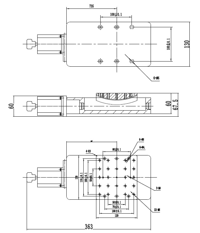
Stepper Motor Driven Mechanical Drawing

|
|
|
Ordering Information
|
Part No.
|
Description
|
Amount
|
|
AK140-15-01
|
Stepper Motor Driven Goniometer Stage,
+/-15 Deg
of rotation,
Table Size 120 mm x130 mm
|
Click to Get a Quote
|
|
AK140-15-02
|
Three Phase Brushless Servo Motor with Quadrature Incremental
Optical Encoder Driven Goniometer Stage,
+/-15 Deg
of rotation,
Table Size 120 mm x130 mm
|
Click to Get a Quote
|
|
AK140-15-03
|
DC ervo Motor with Quadrature Incremental
Optical Encoder Driven Goniometer Stage,
+/-15 Deg
of rotation,
Table Size 120 mm x130 mm
|
Click to Get a Quote
|
|
AK140-15-04
|
Stepper Motor Driven Goniometer Stage
with 500 Cycles per Revolution Quadrature Optical Encoder
Mounted at the back of the Stepper Motor
,
+/-15 Deg
of rotation,
Table Size 120 mm x130 mm
|
Click to Get a Quote
|
|
Related Products
|