|
| |
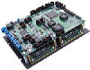
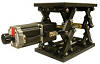
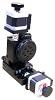
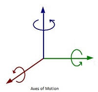
Motorized Three-axis Gimbal Mount,
Azimuth, Elevation and Roll Axes
(Yaw, Pitch and Roll Axes)
|
Home
>
Assorted Motorized Gimbal Mounts
|
|
|
|
|
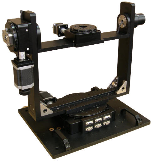
These three-axis, Azimuth, Elevation, Roll, Gimbal Mounts are ideal for mounting: Cameras, antennas, projectors, lasers and instrumentation for scanning, tracking, positioning optics, and other applications.
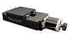
Each axis of the gimbal mount features: Low backlash worm gear drives and precision "V" groove and cross roller bearings for very high repeatability and positional accuracy. Available with either stepper motors (AU400-01 pictured) or with three-phase brushless servo motors with Quadrature Optical Encoders (AU400-02) for greater resolution, accuracy, and repeatability as well as higher travel speeds.
Each AU400 Series Azimuth and Elevation Three-axis Gimbal Mount handles loads to 10kg (22 lb), and the base plate has four handles and accessible predrilled mounting holes for easy integration into new or existing applications. The travel speeds of each axis are 12 Degrees per second with stepper motors and 45 Degrees per second with servo motors. Electrical wiring is enclosed for protection and connections are made using 9 pin DB-9 connectors.
The knobs of the stepper motors may be replaced with optical encoders for position verification.
An
Elevation and Roll Axes version of this gimbal
is available.
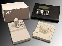
The AU400 Motorized Three-axis Gimbal Mounts require a
Motion Controller
that can be ordered as a complete plug-and-play system with joystick and keypad.

Video Demonstration
|
|
Specifications
|
Type
|
AU400-AER-01
|
|
Structure
Description
|
Range of Travel |
360 Deg Continuous
on All Axes
|
| Table Size |
Diameter: 100 mm (3.937 in)
|
| Gear Ratio |
180:1 |
| Actuator Type |
Worm and Worm Gear |
| Travel Guide |
Precision V-groove & Crossed Roller |
|
Azimuth Motor
|
| |
|
|
Typical Phase Current
|
2 Amp
|
|
DB-9 Male Connector
|
|
Pin Assignment and Description
|
|
1
|
+5 VDC
|
|
2
|
Channel-A of Encoder (Optional) |
|
3
|
Channel-B of Encoder (Optional) |
|
4
|
Common |
|
5
|
HOME Switch, Open Collector, Normally Open, Needs 1K Pull up Resistor |
|
6
|
Stepper Motor Phase A+ |
| 7 |
Stepper Motor Phase A- |
| 8 |
Stepper Motor Phase B+ |
| 9 |
Stepper Motor Phase B- |
|
|
Elevation Motor
|
| Typical Phase Current |
2 Amp |
| |
|
|
DB-9 Male Connector
|
|
Pin Assignment and Description
|
|
1
|
+5 VDC
|
|
2
|
Channel-A of Encoder (Optional) |
|
3
|
Channel-B of Encoder (Optional) |
|
4
|
Common |
|
5
|
HOME Switch, Open Collector, Normally Open, Needs 1K Pull up Resistor |
|
6
|
Stepper Motor Phase A+ |
| 7 |
Stepper Motor Phase A- |
| 8 |
Stepper Motor Phase B+ |
| 9 |
Stepper Motor Phase B- |
|
|
Roll Motor
|
| Typical Phase Current |
1 Amp |
|
DB-9 Male Connector
|
|
Pin Assignment and Description
|
|
1
|
+5 VDC
|
|
2
|
Channel-A of Encoder (Optional) |
|
3
|
Channel-B of Encoder (Optional) |
|
4
|
Common |
|
5
|
HOME Switch, Open Collector, Normally Open, Needs 1K Pull up Resistor |
|
6
|
Stepper Motor Phase A+ |
| 7 |
Stepper Motor Phase A- |
| 8 |
Stepper Motor Phase B+ |
| 9 |
Stepper Motor Phase B- |
|
| |
|
|
Base Material
|
Aluminum Alloy
|
| Surface Treatment |
Black Anodized |
| Load Capacity |
6 kg (14 lb) |
| Weight with the Optional Bottom Plate |
24 kg (52.5 lb) |
|
Weight of the Bottom Plate
|
2.9 kg (6.3 lb)
|
Resolution |
0.001 Deg = 3.6 arcsec (10 Micro-steps per Step Motor Driver in use)
|
|
Maximum Speed of the Azimuth axis with Stepper Motor
|
8 Deg/sec |
|
Maximum Speeds of the Elevation and Roll Axes with Stepper Motors
|
12 Deg/sec |
|
Typical Accuracy
|
|
Accuracy
|
0.05 Deg = 180 arcsec |
|
Repeatability
|
+/-
0.01 Deg = +/- 36 arcsec |
|
Type
|
AU400-AER-02
|
|
Structure Description
|
Range of Travel |
360 Deg Continuous
on Azimuth and Roll Axes
|
| Table Size |
Diameter: 100 mm (3.937 in)
|
| Gear Ratio |
180:1 |
| Actuator Type |
Worm and Worm Gear |
| Travel Guide |
Precision V-groove & Crossed Roller |
|
Azimuth
Axis
|
|
DB-9 Male Connector
|
|
1
|
+5 VDC Input
|
| 2 |
Not Used |
| 3 |
Not Used
|
| 4 |
COMMON, (+5 VDC RETURN, GROUND)
|
| 5 |
Home Switch
for rotary stages
Open Collector or Normally Open
Needs Pull up Resistor (Typically 1000 Ohms)
|
| 6 |
BLDC Motor PHASE A |
| 7 |
BLDC Motor PHASE B
|
| 8 |
BLDC Motor PHASE C
|
| 9 |
Not Used |
|
DB-9 Female Connector
|
| 1 |
+5 VDC Input for HALL Sensors
|
| 2 |
HALL-A Output
|
| 3 |
HALL-B Output
|
| 4 |
HALL-C Output
|
| 5 |
COMMON for HALL Sensors, (+5 VDC RETURN, GROUND)
|
| 6 |
+5 VDC Input for Encoder
|
| 7 |
Encoder-A Output
|
| 8 |
Encoder-B Output
|
| 9 |
COMMON for Encoder, (+5 VDC RETURN, GROUND)
|
|
|
|
|
Elevation
Axis
|
|
DB-9 Male Connector
|
|
1
|
+5 VDC Input
|
| 2 |
Not Used |
| 3 |
Not Used
|
| 4 |
COMMON, (+5 VDC RETURN, GROUND)
|
| 5 |
Home Switch
for rotary stages
Open Collector or Normally Open
Needs Pull up Resistor (Typically 1000 Ohms)
|
| 6 |
BLDC Motor PHASE A |
| 7 |
BLDC Motor PHASE B
|
| 8 |
BLDC Motor PHASE C
|
| 9 |
Not Used |
|
DB-9 Female Connector
|
| 1 |
+5 VDC Input for HALL Sensors
|
| 2 |
HALL-A Output
|
| 3 |
HALL-B Output
|
| 4 |
HALL-C Output
|
| 5 |
COMMON for HALL Sensors, (+5 VDC RETURN, GROUND)
|
| 6 |
+5 VDC Input for Encoder
|
| 7 |
Encoder-A Output
|
| 8 |
Encoder-B Output
|
| 9 |
COMMON for Encoder, (+5 VDC RETURN, GROUND)
|
|
|
|
|
Roll Axis
|
|
DB-9 Male Connector
|
|
1
|
+5 VDC Input
|
| 2 |
Not Used |
| 3 |
Not Used
|
| 4 |
COMMON, (+5 VDC RETURN, GROUND)
|
| 5 |
Home Switch
for rotary stages
Open Collector or Normally Open
Needs Pull up Resistor (Typically 1000 Ohms)
|
| 6 |
BLDC Motor PHASE A |
| 7 |
BLDC Motor PHASE B
|
| 8 |
BLDC Motor PHASE C
|
| 9 |
Not Used |
|
DB-9 Female Connector
|
| 1 |
+5 VDC Input for HALL Sensors
|
| 2 |
HALL-A Output
|
| 3 |
HALL-B Output
|
| 4 |
HALL-C Output
|
| 5 |
COMMON for HALL Sensors, (+5 VDC RETURN, GROUND)
|
| 6 |
+5 VDC Input for Encoder
|
| 7 |
Encoder-A Output
|
| 8 |
Encoder-B Output
|
| 9 |
COMMON for Encoder, (+5 VDC RETURN, GROUND)
|
|
|
|
| Base Material |
Aluminum Alloy |
| Surface Treatment |
Black Anodized |
| Load Capacity |
10 kg (22 lb) |
| Weight |
|
Resolution |
0.001 Deg = 3.6 arcsec (500 Lines per Revolution Encoder in use)
|
|
Maximum Speeds with Servo Motors
|
45
Deg/sec
|
|
Typical Accuracy
|
0.05 Deg = 180 arcsec
|
|
Typical Repeatability
|
+/- 0.01 Deg = +/- 36 arcsec
|
|
|
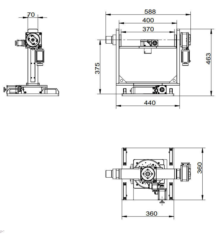
Stepper Motor Driven Mechanical Drawing
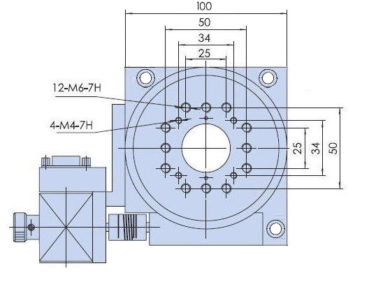
Top Plate Mechanical Drawing
|
|
|
Ordering Information
|
Part No.
|
Description
|
Amount
|
|
AU400-AER-01
|
Stepper
Motor Driven
Three-axis Gimbal Mount, Azimuth, Elevation and Roll Axes
(Yaw, Pitch and Roll Axes), Fork
Width 400 mm
|
Click to Get a Quote
|
|
AU400-AER-02
|
Three Phase Brushless Servo Motor with Quadrature Incremental Optical Encoder Driven
Three-axis Gimbal Mount, Azimuth, Elevation and Roll Axes
(Yaw, Pitch and Roll Axes),
Fork Width 400 mm
|
Click to Get a Quote
|
|
AU400-AER-03
|
DC
Servo Motor with Quadrature Incremental Optical Encoder Driven
Three-axis Gimbal Mount, Azimuth, Elevation and Roll Axes
(Yaw, Pitch and Roll Axes),
Fork Width 400 mm
|
Click to Get a Quote
|
|
AU400-AER-04
|
Stepper
Motor Driven
Three-axis Gimbal Mount,
Azimuth, Elevation and Roll Axes
(Yaw, Pitch and Roll Axes) with
500 Cycles per Revolution
Quadrature Optical Encoders
Mounted at the back of the
Stepper
Motors,
Fork Width 400 mm
|
Click to Get a Quote
|
|
|