|
| |
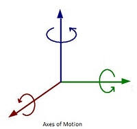
Three-axis Yaw, Pitch and Roll Stage
|
|
Home
>
Motorized Yaw, Pitch and Roll Stages
|
|
|
|
|
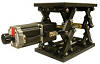
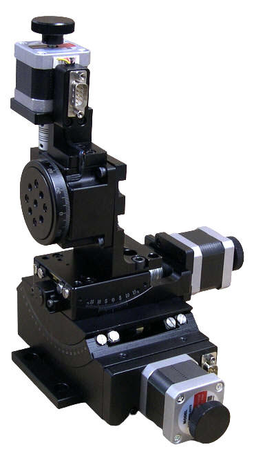
The PYR-45-15-60 Series of Three-axis
Pitch, Yaw,
and Roll
Stages
are the integration of a 60 mm diameter rotary stage (upper axis) capable of 360 Degrees of continuous operation mounted with the table perpendicular to the table of the Yaw stage (middle axis) goniometer. The middle goniometer stage has a range of +/- 15 Degrees and the lower goniometer stage has a +/- 10 Degrees range.
These compact three-axis Pitch, Yaw, and Roll stages feature four motor options to meet the precision and speed of travel requirements of an application.
Depending on the levels of precision and speed of travel requirements, four motor options are available. The Stepper Motor Driven Stage (-01 option pictured) has knobs at the back of the stepper motors for manual adjustments. With a 10 microsteps-per-step motor driver the repeatability of the stages is +/- 0.01 Degrees and travel speeds of 30 Degrees-per-second (roll stage) and 14 Degrees-per-second (yaw and pitch stages) can be achieved. Option -02 is driven by Three Phase-Servo Motors with Quadrature Optical Encoders, and option -03 is Brushed DC Servo Motor Driven with Quadrature Optical Encoders. The servo driven stages in a closed loop offer the highest precision and travel speeds. The -04 option is Stepper Motor Driven with Quadrature Optical Encoders for position verification.
These three axis stages
are the ideal choices for: Optics, laser scanning, drilling, and machining, reverse engineering, inspection, assembly, measurements, tracking, and positioning.
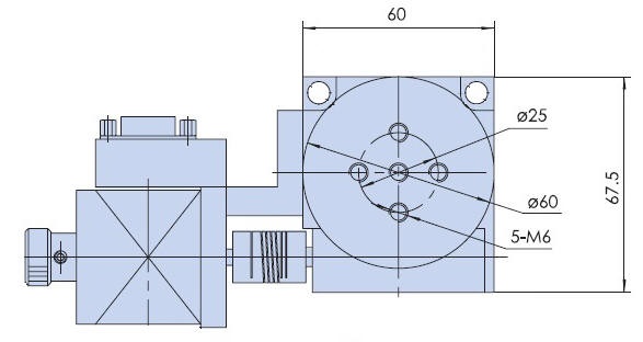
The rotary axis has a precision pattern of threaded holes for mounting tooling or fixtures and is equipped with a HOME switch to signal the motion controller for initial HOME positioning. The goniometer (pitch and yaw) axes are equipped with positive and negative limit switches to signal the motion controller that end of travel is reached. All axes have calibrated scales for visual inspection.
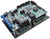
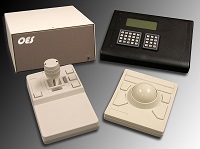
Each of these stages can be ordered with a fully plug-and-play compatible multi-axis
Motion Controller
, joystick and keypad control for any motor combination from OES.
.

Video Demonstration
|
|
|
|
Specifications
| |
PYR-45-15-60
|
|
Total Weight
|
3.5
kg (7.7 lb)
|
|
Load Capacity
|
4.0 kg (8.8 lb)
|
|
Base Material
|
Aluminum Alloy
|
|
Surface Treatment
|
Black Anodized
|
|
|
| Typical Phase Resistance |
3.8 Ohms, Bi-directional |
| Typical Phase Current |
1 Amp |
|
DB-9 Male Connector
|
|
Stepper Motor
|
|
Pin Assignment and Description
|
|
1
|
+5 VDC
|
|
2
|
CCW Limit Switch
, Open Collector, Normally Open, Needs Pull up Resistor
(Pitch and Roll Axes)
|
|
3
|
CW Limit Switch
, Open Collector, Normally Open, Needs Pull up Resistor
|
|
4
|
Common
(Pitch Axis)
|
|
5
|
HOME Switch, Open Collector, Normally Open, Needs 1K Pull up Resistor (Roll Axis)
|
|
6
|
Stepper Motor Phase A+ |
| 7 |
Stepper Motor Phase A- |
| 8 |
Stepper Motor Phase B+ |
| 9 |
Stepper Motor Phase B- |
| |
|
| |
|
| |
|
| |
Yaw (Upper) Axis
|
|
Structure Description
|
|
Range of Travel
|
360 Degrees Continuous
|
|
Gear Ratio |
90:1
|
| Drive Mechanism |
Worm Gear
|
| Travel Guide |
Bearing
|
|
Typical Accuracy
|
|
Resolution
|
0.002 Degrees (10 micro-steps per step stepper motor driver in use)
|
|
Repeatability
|
+/-0.01 Degrees
|
|
Positional Accuracy
|
0.05 Degrees |
|
Maximum Speed with Stepper Motor
|
30 Degrees per second
|
|
Maximum Speed with Servo Motor
|
90 Degrees per second
|
|
|
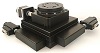
Roll (Middle) Axis
|
|
Structure Description
|
Range of Travel |
+/-15 degrees |
|
Table Size |
65 mm x65 mm
|
|
Gear Ratio |
1 Deg (stage) : 252 Deg (motor)
|
|
Drive Mechanism |
Worm Gear |
|
Travel Guide
|
Crossed-roller Guide |
|
Typical Accuracy
|
|
Resolution
|
Stepper Motor Driver or Servo Motor Optical Encoder Dependent
|
|
Repeatability
|
+/-0.01 Degrees
|
|
Positional Accuracy
|
0.05 Degrees
|
|
Maximum Speed with Stepper Motor
|
14 Degrees per second |
|
Maximum Speed with Servo Motor
|
45 Degrees per second |
|
|
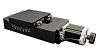
Pitch (Lower) Axis
|
|
Structure Description
|
Range of Travel |
+/-45 degrees |
|
Gear Ratio |
1 Deg (stage) : 296 Deg (motor)
|
|
Drive Mechanism |
Worm Gear |
|
Travel Guide
|
Crossed-roller Guide |
|
Typical Accuracy
|
|
Resolution
|
Stepper Motor Driver or Servo Motor Optical Encoder Dependent
|
|
Repeatability
|
+/-0.01 Degrees
|
|
Positional Accuracy
|
0.05 Degrees
|
|
Maximum Speed with Stepper Motor
|
14 Degrees per second |
|
Maximum Speed with Servo Motor
|
45 Degrees per second |
|
|
|
Stepper Motor Driven Mechanical Drawing (Roll Table)
|
Ordering Information
|
Part No.
|
Description
|
Amount
|
|
PYR45-15-60-01
|
Three
-axis Stepper Motor Driven Yaw, Pitch
and Roll Stage
,
Table Diameter 60 mm
|
Click to Get a Quote
|
|
PYR-45-15-60-02
|
Three
-axis
Three Phase Brushless Servo Motor with Quadrature Incremental
Optical Encoder Driven Yaw, Pitch and Roll Stage, Table Diameter
60 mm
|
Click to Get a Quote
|
|
PYR-45-15-60-03
|
Three
-axis
DC Servo Motor with Quadrature Incremental Optical Encoder
Driven Yaw, Pitch and Roll Stage, Table Diameter 60 mm
|
Click to Get a Quote
|
|
PYR-45-15-60-04
|
Three
-axis Stepper Motor Driven Yaw, Pitch
and Roll Stage
with 500 Cycles per Revolution Quadrature Optical Encoders
Mounted at the back of the Stepper Motors
,
Table Diameter 60 mm
|
Click to Get a Quote
|
Related Products
|