|
|
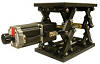
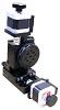
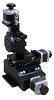
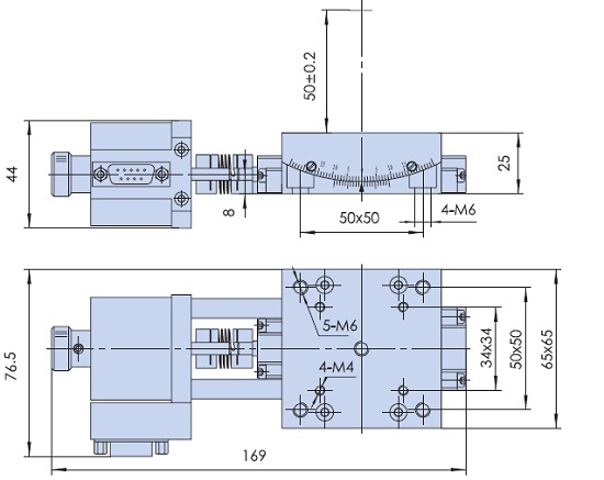
The XAB-xxxx-20-30-01 integrates a two-axis Alpha-Beta goniometer on top of a single-axis linear actuator. The Beta-axis has a travel range of
+/- 15 Degrees with a rotation height of 50 +/- 0.2 mm. The size of the table is 65 by 65 mm (2.559 by 2.559 inches). The gear ratio is 1 Degrees (stage) : 252 Degrees (motor). The travel guide is precision crossed-roller guide.
The lower goniometer (Alpha-axis) has +/- 10 Degrees of rotation driven by a worm gear with a drive ratio of 352 Degrees of motor rotation to 1 degree of stage rotation.
The Alpha and Beta axes have
a caliber indicator to display the angle of rotation which is ideal for: Crystallography, metrology, light measurement, measurement of surgical cutting blades, microscopy, laser positioning, and inspection applications.
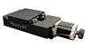
The threaded mounting holes in the Beta-axis and mounting holes in the X axis assure easy integration into new and existing applications.
T
he XAB-xxxx-20-30-01 features Two Phase Stepper Motors with knobs for manual adjustments which can be replaced with optical encoders for position verification. The
XAB-xxxx-20-30-02 is driven by Three Phase Brushless Servo Motors with Quadrature Incremental Optical Encoders for closed loop operation that offer the highest resolution, repeatability, and travel speeds.
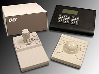
This series requires a
Motion Controller
that can be ordered as a complete plug-and-play system with joystick and keypad.
Specifications
|
Structure
Description
|
Linear Travel |
|
X-axis Range of Travel (mm)
|
Pitch of Lead Screw
|
Resolution
|
Maximum Speed
|
| 15 |
1
mm per turn
|
0.5 microns (10 Micro-steps per Step Motor Driver in use) |
15 mm / sec
|
| 30 |
1
mm per turn
|
0.5 microns (10 Micro-steps per Step Motor Driver in use) |
15 mm / sec |
| 50 |
1
mm per turn
|
0.5 microns (10 Micro-steps per Step Motor Driver in use) |
15 mm / sec |
| 75 |
1
mm per turn
|
0.5 microns (10 Micro-steps per Step Motor Driver in use) |
15 mm / sec |
| 100 |
4
mm per turn
|
2 microns (10 Micro-steps per Step Motor Driver in use) |
50 mm / sec
|
| 150 |
4
mm per turn
|
2 microns (10 Micro-steps per Step Motor Driver in use) |
50 mm / sec
|
| 200 |
4
mm per turn
|
2 microns (10 Micro-steps per Step Motor Driver in use) |
50 mm / sec
|
| 300 |
4
mm per turn
|
2 microns (10 Micro-steps per Step Motor Driver in use) |
50 mm / sec
|
| 400 |
4
mm per turn
|
2 microns (10 Micro-steps per Step Motor Driver in use) |
50 mm / sec
|
| 500 |
4
mm per turn
|
2 microns (10 Micro-steps per Step Motor Driver in use) |
50 mm / sec
|
| 600 |
4
mm per turn
|
2 microns (10 Micro-steps per Step Motor Driver in use) |
50 mm / sec
|
| 700 |
4
mm per turn
|
2 microns (10 Micro-steps per Step Motor Driver in use) |
50 mm / sec
|
| 800 |
4
mm per turn
|
2 microns (10 Micro-steps per Step Motor Driver in use) |
50 mm / sec
|
| 900 |
4
mm per turn
|
2 microns (10 Micro-steps per Step Motor Driver in use) |
50 mm / sec
|
| 1000 |
4
mm per turn
|
2 microns (10 Micro-steps per Step Motor Driver in use) |
50 mm / sec
|
|
|
Alpha-axis
Range of Travel
|
+/-10 Degrees
|
|
Beta-axis Range of Travel
|
+/-15 Degrees
|
| Travel Guide |
High Precision Crossed Roller |
| Motor
|
| |
|
Typical Phase Resistance
|
3.8 Ohms, Bi-directional
|
| Typical Phase Current |
1 Amp |
|
DB-9 Male Connector
|
|
Pin Assignment and Description
|
| 1 |
+5 VDC for the Limit Sensors |
| 2 |
CCW Limit Switch, Open Collector, Normally Open, Needs Pull up Resistor (1000 Ohms)
|
| 3 |
CW Limit Switch, Open Collector, Normally Open, Needs Pull up Resistor (1000 Ohms)
|
| 4 |
Return for+5 VDC
|
|
5
|
Not Connected
|
|
6
|
Stepper Motor Phase A+ |
| 7 |
Stepper Motor Phase A- |
| 8 |
Stepper Motor Phase B+ |
| 9 |
Stepper Motor Phase B- |
|
|
Body Material
|
Aluminum Alloy |
|
Surface Treatment
|
Black Anodized |
|
Typical Accuracy
|
Resolution |
Configuration Dependent |
|
Maximum Speed
|
5 mm / sec
|
| Repeatability |
10 microns
|
|
Positional Accuracy
|
10 microns
|
|
Accessories
Description
|
Optional Optical Encoders
Optional Servo Motors
Other Sizes and Strokes Available
|
|
|