|

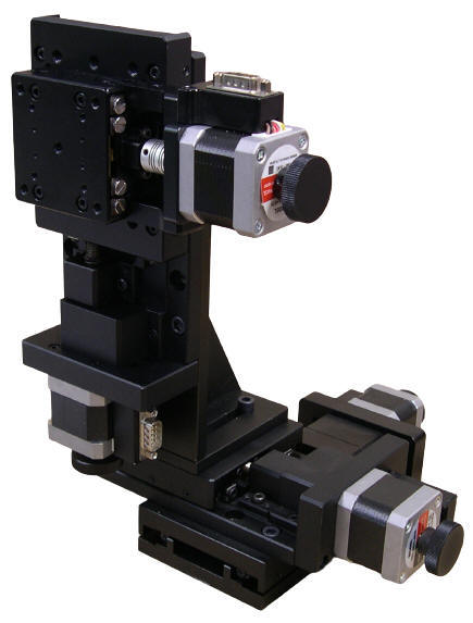
Any of the four Goniometer Stages with +/- 10 Degrees, +/- 15 Degrees,
+/- 30 Degrees
or +/- 45 Degrees of travel can be integrated with X, Y, and Z axis stages with 15 mm, 30 mm, 50 mm, 75 mm, or larger than 100 mm of linear travel linear in any combination
of X, Y, and Z axes. These stages are
the ideal choices for: Crystallography, metrology, light measurement, mirror positioning, laser scanning, drilling and machining, reverse engineering, inspection, assembly, measurements, tracking, and inspection and optical bench applications.
Each axis of these black anodized aluminum alloy stages features high precision crossed roller bearings. The 15 mm, 30 mm, 50 mm, 75 mm linear axes feature high precision 1 mm per turn lead screws and the larger than 100 mm linear travel stage has a 4 mm per turn lead screw. For higher resolutions and greater travel speeds servo motors are available.
This series of four axes stages feature four motor options. The -01 option is Stepper Motor driven, the -02 option is Three Phase-Servo Motor driven with a Quadrature Optical Encoder, the -03 is DC Servo Motor Driven with a Quadrature Optical Encoder, and the -04 option is Stepper Motor Driven with Quadrature Optical Encoders for position verification.
The Goniometer axis is equipped with a HOME switch to signal the motion controller the ZERO position. Each Goniometer axis can be mounted for horizontal (pictured) or vertical rotation, and they have a pattern of precision mounting holes for mounting fixtures, mirrors, etc. The linear axes are equipped with limit switches to signal the motion controller that end of travel is reached.
Each of these stages can be ordered with a fully plug-and-play compatible multi-axis motion controller for any motor combination from OES.
|
Specifications
|
Structure
Description
|
Linear Travel |
|
Range of Travel (mm)
|
Pitch of Lead Screw
|
| 15 |
1
mm per turn
|
| 30 |
1
mm per turn
|
| 50 |
1
mm per turn
|
| 75 |
1
mm per turn
|
| Longer
than 100 |
4
mm per turn
|
|
|
Goniometer Range of Travel
|
+/-10 Degrees
+/-15 Degrees
+/-30 Degrees
|
|
+/-45 Degrees
|
| Travel Guide |
High Precision Crossed Roller |
| Motor

|
| |
|
Typical Phase Resistance
|
3.8 Ohms, Bi-directional
|
| Typical Phase Current |
1 Amp |
|
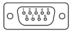
DB-9 Male Connector
|
|
Pin Assignment and Description
|
| 1 |
+5 VDC for the Limit Sensors |
| 2 |
CW Limit Switch, Open Collector, Normally Open, Needs Pull up Resistor (1000 Ohms)
|
| 3 |
CCW Limit Switch, Open Collector, Normally Open, Needs Pull up Resistor (1000 Ohms)
|
| 4 |
Return for+5 VDC
|
|
5
|
Not Connected
|
|
6
|
Stepper Motor Phase A+ |
| 7 |
Stepper Motor Phase A- |
| 8 |
Stepper Motor Phase B+ |
| 9 |
Stepper Motor Phase B- |
|
|
Body Material
|
Aluminum Alloy |
|
Surface Treatment
|
Black Anodized |
|
Typical Accuracy
|
Resolution |
Configuration Dependent |
|
Maximum Speed
|
5 mm / sec
|
| Repeatability |
10 microns
|
|
Positional Accuracy
|
10 microns
|
|
Accessories
Description
|
Optional Optical Encoders
Optional Servo Motors
Other Sizes and Strokes Available
|
|
|
|
Part No.
|
Description
|
Amount
|
|
XYZG-xxxx-yyyy-zzzz-gg-01
|
Stepper Motor Driven
XYZ-axis plus Vertical Goniometer Stage
xxxx denotes the
stroke of the X-axis in mm.
yyyy
denotes the
stroke of the Y-axis in mm.
zzzz denotes the stroke of the Z-axis in mm.
gg donates the goniometer's
total r
ange
of travel
in
Degrees, 20 Degrees, 30 Degrees, 60 Degrees or 90 Degrees.
|
Click to Get a Quote
|
|
XYZG-xxxx-yyyy-zzzz-gg-02
|
Three Phase Brushless Servo Motor with Quadrature Incremental
Optical Encoder Driven
XYZ-axis plus Vertical Goniometer Stage
xxxx denotes the
stroke of the X-axis in mm.
yyyy denotes the
stroke of the Y-axis in mm.
zzzz denotes the stroke of the Z-axis in mm.
gg donates the goniometer's
total r
ange
of travel
in
Degrees, 20 Degrees, 30 Degrees, 60 Degrees or 90 Degrees.
|
Click to Get a Quote
|
|
XYZG-xxxx-yyyy-zzzz-gg-03
|
Stepper Motor Driven
XYZ-axis plus Vertical Goniometer Stage
xxxx denotes the
stroke of the X-axis in mm.
yyyy denotes the
stroke of the Y-axis in mm.
zzzz denotes the stroke of the Z-axis in mm.
gg donates the goniometer's
total r
ange
of travel
in
Degrees, 20 Degrees, 30 Degrees, 60 Degrees or 90 Degrees.
|
Click to Get a Quote
|
|
XYZG-xxxx-yyyy-zzzz-gg-04
|
Three Phase Brushless Servo Motor with Quadrature Incremental
Optical Encoder Driven
XYZ-axis plus Vertical Goniometer Stage
xxxx denotes the
stroke of the X-axis in mm.
yyyy denotes the
stroke of the Y-axis in mm.
zzzz denotes the stroke of the Z-axis in mm.
gg donates the goniometer's
total r
ange
of travel
in
Degrees, 20 Degrees, 30 Degrees, 60 Degrees or 90 Degrees.
|
Click to Get a Quote
|
|
|
|
|
|
|