|
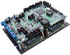
Product Highlight
|
|
Min.
|
Max.
|
|
Number of Axis
|
1
|
4
|
|
Speed Range, Revolution per Second (RPS)
|
0.02
|
40.0
|
|
Motor Current (Peak), Amp
|
0.15
|
7.0*
|
|
Steps / Revolution (200
Steps per Rev. stepping Motor)
|
400
|
51200
|
|
Micro-stepping Resolution, Micro-steps per Step
|
2
|
256
|
Motor Torque, oz-in
N-m
|
7
0.050
|
2100
15.0
|
|
Line Voltage, VAC
|
115
|
230
|
|
Line Frequency, Hz
|
50
|
60
|
|
Power Supply Voltage, VDC
|
24
|
80
|
X-Motor
8-pin Circular Connector
The X-axis motor should be connected to this connector.
|
PIN
|
NAME
|
Stepping Motor
|
DC MOTOR
|
BRUSHLESS DC MOTOR
|
|
1
|
PHAX+
|
Stepper Motor Phase A+
|
Arm+
|
Phase A
|
|
2
|
PHBX+
|
Stepper Motor Phase B+
|
Not Connected
|
Phase B
|
|
3
|
PHBX-
|
Stepper Motor Phase B-
|
Not Connected
|
Not Connected
|
|
4
|
PHAX-
|
Stepper Motor Phase A-
|
Arm-
|
Phase C
|
|
5
|
CHSIS
|
Connected to the Chassis
|
Connected to the Chassis
|
Connected to the Chassis
|
|
6
|
|
Not Connected
|
Not Connected
|
Not Connected
|
|
7
|
|
Not Connected
|
Not Connected
|
Not Connected
|
|
8
|
|
Not Connected
|
Not Connected
|
Not Connected
|
Y-Motor
8-pin Circular Connector
The Y-axis motor should be connected to this connector.
|
PIN
|
NAME
|
Stepping Motor
|
DC MOTOR
|
BRUSHLESS DC MOTOR
|
|
1
|
PHAY+
|
Stepper Motor Phase A+
|
Arm+
|
Phase A
|
|
2
|
PHBY+
|
Stepper Motor Phase B+
|
Not Connected
|
Phase B
|
|
3
|
PHBY-
|
Stepper Motor Phase B-
|
Not Connected
|
Not Connected
|
|
4
|
PHAY-
|
Stepper Motor Phase A-
|
Arm-
|
Phase C
|
|
5
|
CHSIS
|
Connected to the Chassis
|
Connected to the Chassis
|
Connected to the Chassis
|
|
6
|
|
Not Connected
|
Not Connected
|
Not Connected
|
|
7
|
|
Not Connected
|
Not Connected
|
Not Connected
|
|
8
|
|
Not Connected
|
Not Connected
|
Not Connected
|
Z-Motor
8-pin Circular Connector
The Z-axis motor should be connected to this connector.
|
PIN
|
NAME
|
Stepping Motor
|
DC MOTOR
|
BRUSHLESS DC MOTOR
|
|
1
|
PHAZ+
|
Stepper Motor Phase A+
|
Arm+
|
Phase A
|
|
2
|
PHBZ+
|
Stepper Motor Phase B+
|
Not Connected
|
Phase B
|
|
3
|
PHBZ-
|
Stepper Motor Phase B-
|
Not Connected
|
Not Connected
|
|
4
|
PHAZ-
|
Stepper Motor Phase A-
|
Arm-
|
Phase C
|
|
5
|
CHSIS
|
Connected to the Chassis
|
Connected to the Chassis
|
Connected to the Chassis
|
|
6
|
|
Not Connected
|
Not Connected
|
Not Connected
|
|
7
|
|
Not Connected
|
Not Connected
|
Not Connected
|
|
8
|
|
Not Connected
|
Not Connected
|
Not Connected
|
W-Motor
8-pin Circular Connector
The W-axis motor should be connected to this connector.
|
PIN
|
NAME
|
Stepping Motor
|
DC MOTOR
|
BRUSHLESS DC MOTOR
|
|
1
|
PHAW+
|
Stepper Motor Phase A+
|
Arm+
|
Phase A
|
|
2
|
PHBW+
|
Stepper Motor Phase B+
|
Not Connected
|
Phase B
|
|
3
|
PHBW-
|
Stepper Motor Phase B-
|
Not Connected
|
Not Connected
|
|
4
|
PHAW-
|
Stepper Motor Phase A-
|
Arm-
|
Phase C
|
|
5
|
CHSIS
|
Connected to the Chassis
|
Connected to the Chassis
|
Connected to the Chassis
|
|
6
|
|
Not Connected
|
Not Connected
|
Not Connected
|
|
7
|
|
Not Connected
|
Not Connected
|
Not Connected
|
|
8
|
|
Not Connected
|
Not Connected
|
Not Connected
|
* Motor current
up to 10 Amp. is available.
X-Encoder
9-pin DB-9, Male Connector
The X-axis motor encoder and Hall effect sensors, if available, should
be connected to this port.
|
PIN
|
NAME
|
DESCRIPTION
|
|
1
|
+5 VDC
|
+5 VDC
|
|
2
|
CHSIS
|
Connected to the Chassis
|
|
3
|
XCHB
|
X-Motor Channel-B Quadrature Input
|
|
4
|
XCHA
|
X-Motor Channel-A Quadrature Input
|
|
5
|
GND
|
System Ground
|
|
6
|
XHALL-B
|
X-Motor HALL-B Sensor Input
|
|
7
|
XHALL-C
|
X-Motor HALL-C Sensor Input
|
|
8
|
XHALL-A
|
X-Motor HALL-A Sensor Input
|
|
9
|
|
Not Connected
|
Y-Encoder
9-pin DB-9, Male Connector
The Y-axis motor encoder and Hall effect sensors, if available, should
be connected to this port.
|
PIN
|
NAME
|
DESCRIPTION
|
|
1
|
+5 VDC
|
+5 VDC
|
|
2
|
CHSIS
|
Connected to the Chassis
|
|
3
|
YCHB
|
Y-Motor Channel-B Quadrature Input
|
|
4
|
YCHA
|
Y-Motor Channel-A Quadrature Input
|
|
5
|
GND
|
System Ground
|
|
6
|
YHALL-B
|
Y-Motor HALL-B Sensor Input
|
|
7
|
YHALL-C
|
Y-Motor HALL-C Sensor Input
|
|
8
|
YHALL-A
|
Y-Motor HALL-A Sensor Input
|
|
9
|
|
Not Connected
|
Z-Encoder
9-pin DB-9, Male Connector
The Z-axis motor encoder and Hall effect sensors, if available, should
be connected to this port.
|
PIN
|
NAME
|
DESCRIPTION
|
|
1
|
+5 VDC
|
+5 VDC
|
|
2
|
CHSIS
|
Connected to the Chassis
|
|
3
|
ZCHB
|
Z-Motor Channel-B Quadrature Input
|
|
4
|
ZCHA
|
Z-Motor Channel-A Quadrature Input
|
|
5
|
GND
|
System Ground
|
|
6
|
ZHALL-B
|
Z-Motor HALL-B Sensor Input
|
|
7
|
ZHALL-C
|
Z-Motor HALL-C Sensor Input
|
|
8
|
ZHALL-A
|
Z-Motor HALL-A Sensor Input
|
|
9
|
|
Not Connected
|
W-Encoder
9-pin DB-9, Male Connector
The W-axis motor encoder and Hall effect sensors, if available, should
be connected to this port.
|
PIN
|
NAME
|
DESCRIPTION
|
|
1
|
+5 VDC
|
+5 VDC
|
|
2
|
CHSIS
|
Connected to the Chassis
|
|
3
|
WCHB
|
W-Motor Channel-B Quadrature Input
|
|
4
|
WCHA
|
W-Motor Channel-A Quadrature Input
|
|
5
|
GND
|
System Ground
|
|
6
|
WHALL-B
|
W-Motor HALL-B Sensor Input
|
|
7
|
WHALL-C
|
W-Motor HALL-C Sensor Input
|
|
8
|
WHALL-A
|
W-Motor HALL-A Sensor Input
|
|
9
|
|
Not Connected
|
Input
- Output Connection
25-pin
DB-25, female Connector
|
PIN
|
NAME
|
DESCRIPTION
|
|
2
|
STEP-X
|
X-Axis Step Signal
|
|
3
|
DIR-X
|
X-Axis Direction
Signal
|
|
4
|
STEP-Y
|
Y-Axis Step
Signal
|
|
5
|
DIR-Y
|
Y-Axis Direction
Signal
|
|
6
|
STEP-Z
|
Z-Axis Step
Signal
|
|
7
|
DIR-Z
|
Z-Axis Direction
Signal
|
|
8
|
STEP-W
|
W-Axis Step
Signal
|
|
9
|
DIR-W
|
W-Axis Direction
Signal
|
|
23
|
GND
|
System
Ground
|
|
24
|
GND
|
System
Ground
|
|
25
|
GND
|
System
Ground
|
|